Gearmotor Maintenance: Advanced Techniques
In today’s industry, gearmotors play an essential role in a wide range of applications – from process automation in the manufacturing industry to energy efficiency in transportation systems. These machines combine the power of an electric motor with the versatility of a gearbox, enabling them to reduce speed and increase torque to adapt to different processes. However, to ensure optimum performance and long life, proper gearmotor maintenance is essential.
In an industrial environment, mechanical components are exposed to wear, heat, humidity and other factors that can negatively affect their operation. That is why having advanced maintenance techniques that go beyond conventional practices is key.
This article presents a comprehensive overview of advanced maintenance techniques for gearmotors, focusing on how to maximize operational efficiency and minimize unplanned downtime. Besides, we’ll explore different approaches, tools and emerging technologies that are transforming the way maintenance is carried out in this field.
What Is a Gearmotor?
Gearmotors are mechanical elements widely used to drive all types of machines and industrial assets that need to reduce their speed efficiently, constantly and safely.
The gearmotor is essentially used in industrial processes to reduce speed. It does that by means of the gearbox inside it, allowing the input speed to be manipulated to obtain a different output speed. This enables the machine to reach a suitable speed, and helps prevent damage to the equipment to which it is coupled.
Geared motors are ideal for applications that require slow, powerful movements, such as conveyor belts, lifting systems, handling equipment, industrial robots, and many others.
It’s worth noting that gearmotors can have different characteristics according to their specifications, such as gear ratio, type of motor used, and assembly efficiency. When selecting a geared motor for a specific application, it is necessary to carefully consider the torque, speed, and performance requirements needed to ensure optimal system operation.
How Does a Gearmotor Work?
There are two main parts in a gearmotor: the electric motor and the gearbox. The electric motor, usually an alternating current or direct current engine, is responsible for generating the initial movement and the energy to drive the system. The gearbox, on the other hand, contains a series of gears of different sizes and numbers of teeth.
When electrical energy is applied to the motor, it starts to rotate. The generated energy is transferred to the gearbox via an output shaft. Inside the gearbox, the gears interact to reduce the speed of the output shaft while increasing the torque. The ratio between the number of teeth on the gears determines the output speed and the resulting torque.
The input gear, connected directly to the motor shaft, is called the pinion, and the output gear, connected to the output shaft, is called the crown. The arrangement and number of middle gears can vary according to the gearmotor’s design and specifications.
The purpose of the gears is to transfer the motor’s power to the mechanism or machine being driven.
Learn More: Induction Motors, An Industry Revolution
Types of Gearmotors
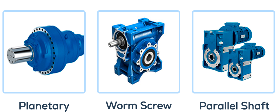
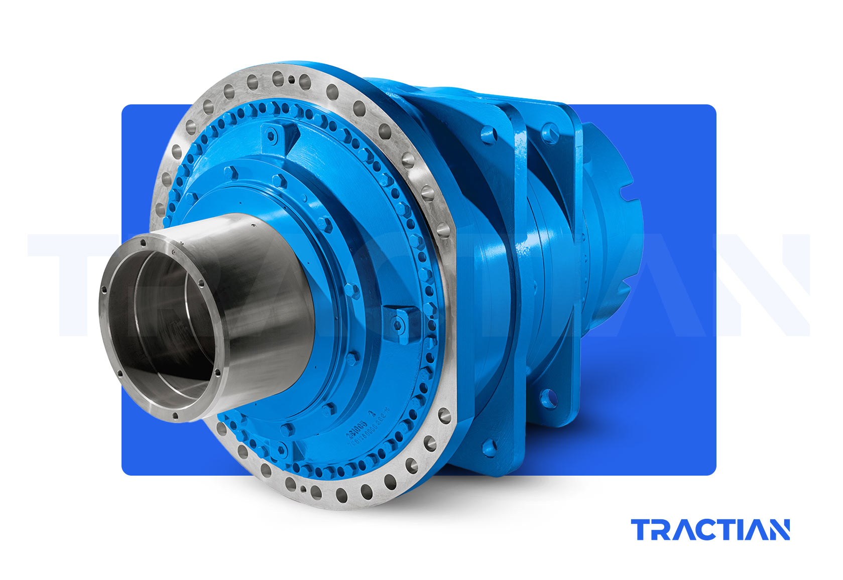
- Planetary Gearbox
A planetary gearmotor, also known as a planetary gearbox or planetary gear, is a specific type of gearmotor that uses a set of planetary gears to achieve speed reduction and torque increase. It is characterized by its compact design, high efficiency and ability to transmit large torque loads.
The planetary gearmotor consists of three main components:
- Sun: central gear, usually disc-shaped, located in the center of the system. Directly connected to the motor shaft, it is the element that drives the initial rotation.
- Planets: smaller gears that rotate around the sun in the same plane, hence the name “planetary gear”. These gears are mounted on shafts called arms or planet carriers. The planets have a gear relationship with the sun, which determines how the movement will be transmitted to the next component.
- Crown or Ring: external and static component of the system. It is serrated on the inside and surrounds the planets. The crown’s teeth mesh with the planets, thus ensuring that the rotation of the planets is transmitted to the ring, sending the output through the gearbox’s output shaft.
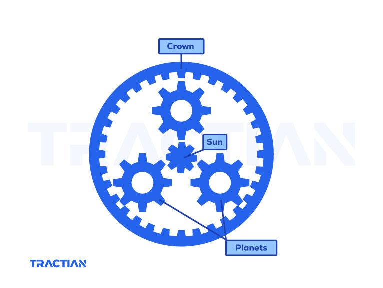
The working principle of a planetary gearmotor is based on the combined movements of the planets and the sun. As the motor rotates the sun, the planets around it also turn. The arrangement of the gears and their speed ratios allow the planets to rotate around their own axis while rotating around the sun. This creates an orbital motion that transmits movement and torque through the ring, achieving a reduction in speed and an increase in output torque.
The planetary arrangement of the gears makes it possible to distribute the load between multiple teeth, improving load capacity and reducing gear fatigue. This makes planetary gearmotors ideal for applications requiring high levels of precision and durability.
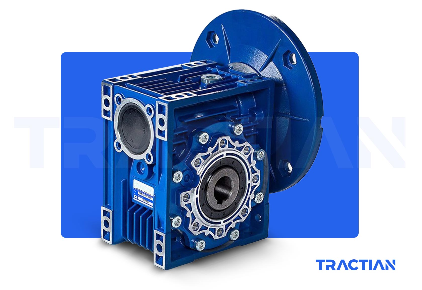
- Worm Screw and Crown Gearmotor
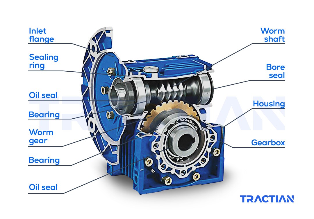
A worm screw and crown gearmotor is made up of two key elements: a worm screw and a gear.
- Worm Screw: elongated helix-shaped part connected to the motor shaft. It is a helical cylindrical gear with a single thread that transmits the rotary movement of the motor to the crown. The helical arrangement of the worm screw creates a thrust and rotation action, which allows it to significantly reduce the output speed compared to the motor speed.
- Crown or gear wheel: large circular gear wheel with teeth arranged on its periphery. These teeth mesh with the worm screw, allowing the rotation to be transmitted to the crown. The arrangement of the teeth and worm determines the transmission ratio between the motor’s input speed and the gearbox’s output speed.
This design provides a significant increase in output torque, making it suitable for applications requiring high power in a compact space, such as lifting systems.
- Parallel Shaft Gearmotor
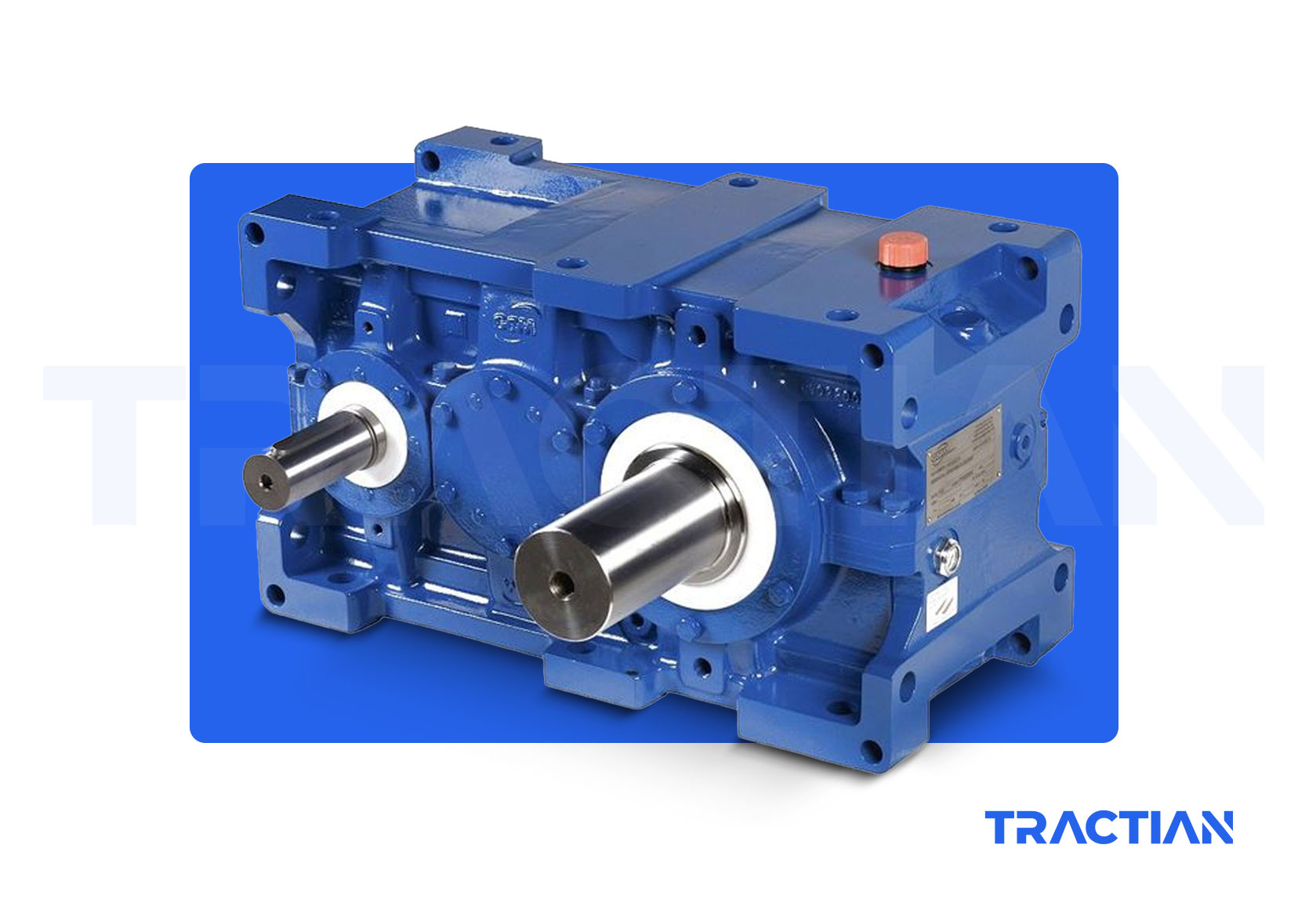
A parallel shaft gearmotor is a type of mechanical transmission system that uses an arrangement of gears to reduce rotational speed and increase output torque in the same plane, i.e. with parallel input and output shafts. This type of geared motor is widely used in various industrial and mechanical applications where high efficiency, compact design and reliable power transmission are required.
The configuration of a parallel shaft gearmotor generally consists of two shafts placed parallel to each other inside the gearbox housing. One of the shafts is connected to the electric motor, while the other is the output shaft that transmits movement to the machinery or system to be driven.
Inside the gearmotor housing are the gears that make power transmission possible. These gears can be of different types, such as straight, helical or bevel gears, depending on the design and specifications of the gearbox. The gears are arranged so that there is a reduction in speed and an increase in torque between the input shaft and the output shaft.
The operation of a parallel shaft gearmotor is based on the interaction between the gear teeth. When the electric motor rotates the input shaft, the gears transfer the movement to the output shaft, but with a reduced speed and an increase in output torque. The transmission ratio between input and output speed is determined by the characteristics of the gears used.
This type of gearmotor is a valuable solution for applications that require greater output power in relation to input speed.
Advanced Maintenance Techniques for Gearmotors
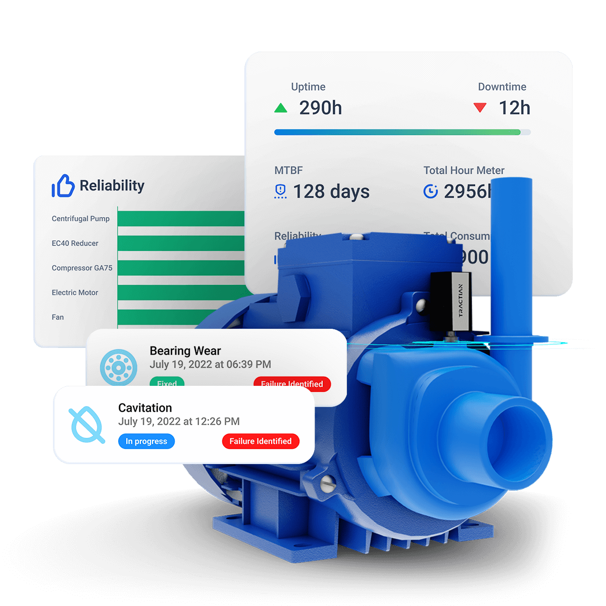
Proper gearmotor maintenance is essential to ensure optimum performance and long life for these assets. Advanced maintenance techniques for gearmotors aim to maximize operational efficiency and minimize unplanned downtime. We will now look at some of the most commonly used techniques:
Vibration Analysis
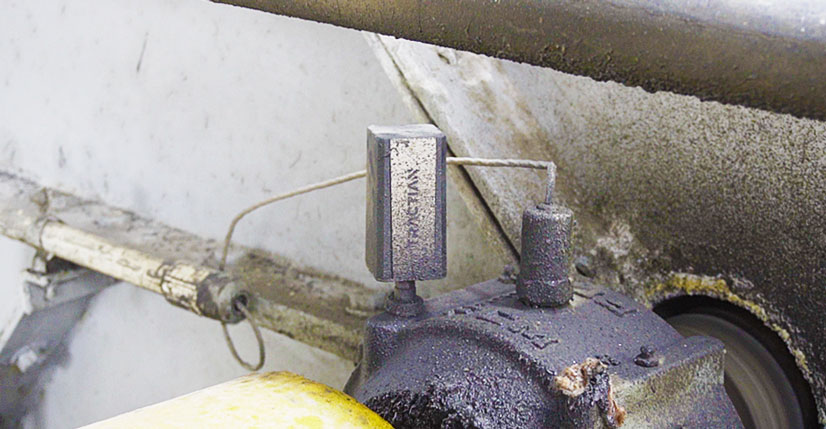
Vibration analysis is a key tool in the predictive maintenance of industrial machinery in general, including gearmotors.
It allows problems to be detected at an early stage by monitoring the vibrations generated by machines.
An abnormal increase in vibration can indicate unbalances, misalignment, looseness, excessive wear or other potential problems that could lead to equipment failure.
The vibration analysis process for gearmotors involves several key steps:
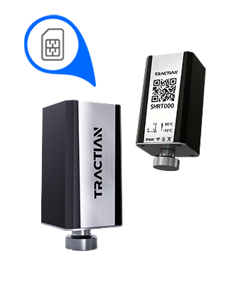
- Data Collection: Vibration sensors are installed in strategic points on the gearmotor to measure vibration generated during normal operation.
- Continuous Condition Monitoring: The sensors record vibrations over time while the gearmotor is in operation. This can be under full load conditions or at different load levels to assess behavior in different operating situations.
- Frequency Spectrum Analysis: The sampled data is converted into a frequency spectrum by means of Fourier analysis.
This spectrum shows vibration frequencies and can reveal characteristic patterns associated with different types of faults.
- Baseline Comparison: The current spectrum is compared with a baseline previously established for the machine under ideal conditions. Any significant deviation can indicate potential problems.
- Diagnosis and Problem Identification: Based on the frequency patterns observed, a diagnosis is carried out to identify the fault.
For example, a peak at a specific frequency may suggest misalignment, while a scattered vibration pattern may indicate general wear.
- Prioritization and Maintenance Planning: Depending on the severity of the problem, a priority for maintenance can be established. More critical problems may require immediate action, while others can be planned for future inspections or repairs.
- Follow-up and Confirmation: After the maintenance actions have been performed, follow-up is carried out to check that the vibrations have subsided and that the problem has been solved.
Learn More About Vibration Analysis
Thermography
Thermography is another valuable technique used in gearmotor predictive maintenance. This technique is based on detecting temperature differences on the surface of an object or piece of equipment in order to identify possible problems and anomalies.
It can be applied as follows:
- Preparation and Equipment: A thermographic camera is required, since it’s capable of capturing infrared images that represent temperature variations. It is crucial that the gearmotor is operating under normal load and operating conditions in order to obtain accurate measurements.
- Image Capture: Images of the surface of the gearmotor and its components must be captured while it’s running. It is necessary to capture images from different angles and distances to get a complete view of the machine.
- Image Analysis: Thermographic analysis software is used to process the captured images and generate temperature maps. The colors on the temperature map indicate variations; warmer colors (such as red and yellow) represent warmer areas, and cooler colors (such as blue and green) represent colder areas.
- Reference Comparison: Current thermographic images are compared with reference images captured when the gearmotor was in ideal condition. This identifies areas where temperatures are higher or lower than normal.
- Interpreting Results: Look for abnormal patterns in thermographic images, such as hot or cold spots, irregular temperature gradients or areas with thermal fluctuations. These patterns can indicate problems such as overheating, bearing wear, excessive friction or unbalances.
- Problem Diagnosis: Use the information from thermographic images to identify and diagnose possible problems in the gearmotor. For example, hot spots can indicate excessive friction due to lubrication problems, while cold areas can indicate power flow problems or component damage.
- Determining Maintenance Actions: Based on the diagnosis, plan and prioritize the necessary maintenance measures. Actions may include proper lubrication, bearing replacement, component adjustment or additional repairs.
- Monitoring and Confirmation: After the maintenance actions have been carried out, new thermographic images should be captured to check whether the temperature differences have decreased or disappeared.
Lubricant Analysis
Last but not least, lubricant analysis is a crucial tool in predictive gearmotor maintenance, as it allows for improving the reliability and efficiency of machines. Here are some points to consider when carrying out proper lubricant analysis:
- Selection of Sampling Points: Identify the strategic points for taking lubricant samples, such as the gearmotor housing and bearings. Follow the manufacturer’s recommendations and previous experience to select the appropriate points.
- Sampling Frequency: Establish a regular and consistent sampling frequency, according to operating conditions and the lubricant’s life cycle. The frequency can vary from monthly to quarterly, depending on the criticality and working environment.
- Sampling Method: Use clean and appropriate sampling techniques to avoid contamination. Use clean tools and suitable collection containers to minimize the introduction of contaminants.
- Physical-chemical Analysis: Carry out tests on viscosity, water content, solid particle content, and other physical-chemical parameters. These analyses help determine the overall quality of the lubricant and its ability to protect the gearmotor’s components.
- Wear Analysis: Use techniques such as optical emission spectrometry or mass spectrometry to identify metals and wear elements in the lubricant. Compare the results with reference limits to detect early signs of wear in bearings, gears or other components.
- Contamination and Contaminants: Assess the presence of external contaminants, such as water, dust particles or combustion products, which could affect the quality of the lubricant and the operation of the gearmotor.
- Result Interpretation: Compare the values obtained with the lubricant manufacturer’s specifications and industry standards. Look for trends in the results over time, which may indicate changes in the gearmotor’s condition.
- Diagnosis and Maintenance Actions: Based on the analysis results, diagnose potential problems such as excessive wear, contamination or lubricant degradation. Determine the necessary maintenance actions, such as changing the lubricant, filtering, cleaning or repairing components.
- Registration and Follow-up: Keep a detailed record of all lubricant analyses carried out, including the results and actions taken. Use these records to keep track of gearmotor health and make informed decisions in future analyses.
- Training and Collaboration: Make sure that the team responsible for lubricant analysis is trained in interpreting results and making maintenance decisions. Collaborate with lubrication and maintenance experts to get advice on complex problems.
Understand All About AI-Assisted Maintenance
In addition to these advanced maintenance techniques, it’s always essential to implement technologies such as maintenance management software and machine condition monitoring sensors, which help make more efficient decisions in maintenance routines.
Share this article

About the author:


Erik Cordeiro
Electrical engineer graduated from the Federal University of São Carlos, specialized in industrial maintenance and energy management. He is an applications engineer at TRACTIAN.

Share this article

Are maintenance breakdowns affecting your bottom line?
Enter your email to let our experts help you reduce costs now
Almost there, !
We just need a few more informations: